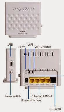
ZTE ADSL MODEM
Model: ZXHN H108N Series
Default IP Address : 192.168.1.1
+ Click the Quick Setup Guide menu
- Type a desired Connection Name
- Create or Select Preconfigure VPI/VCI
- Select Connection Type, Route or Bridge
since we will configure Router Modem, select Route mode
- Select IP as link type
- Select Static as IP Type
- Select IPV4 box and enter the Point-to-point IP Address
or the WAN IP Address and DNS
- then click next button
- Select or Disable/Enable RF Radio then click Next button
- Leave Admin User/Password as-is or modify to your configuration
+ Click Network Menu
- Delete all Connection name and left the recently configured
Wan Connection for PATH-WAN-WAN Connection
- Select LAN menu
- Enter the LAN iP Address
- Select Disable/Enable DHCP Server
- Click Submit button
+ Click SSID Settings under Network/WLAN menu
- Choose SSID name
- Enable the SSID Number
- Select Maximum clients to 16
- Configure a desire SSID Name for a particular SSID Number
- Repeat configuration for SSID 2 - 4 if enabled
+ If DHCP server is enable
+ Configure the DHCP IP Address
- DHCP Start IP Address : 192.168.1.100 (e.g.)
- DHCP Stop IP Address : 192.168.1.116 (e.g.)
- Click DHCP Port Service under Network/LAN menu
- Click SSID 1 to 4 (try to configure Start/Stop IP with 16 IP
per SSID if all SSID was selected)
+ Click Routing (IPV4)
- Select WAN Connection name then click Submit button.
+ Select the Firewall under Security menu
- click enable Anti-Hacking Protection
- Select Firewall level to Low or desired protection

.jpg)


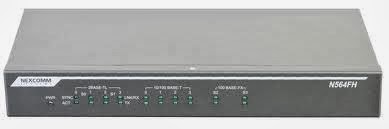
 If your planning to setup an IP Radio link using Airspan, here is a sample config or a guide that might be used.